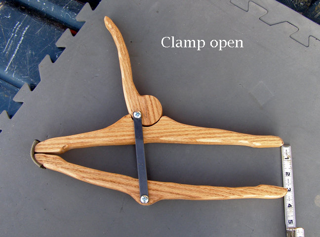
The clamp of strange name but has incredibly large utilization: the cam clamp. This clamp is not the ideal or the most excellent replacement for other better known clamps, but it is almost always the cheapest, most practical and the simplest clamp of all.
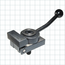
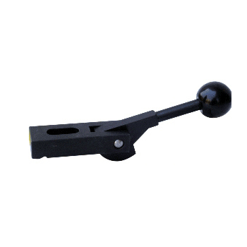
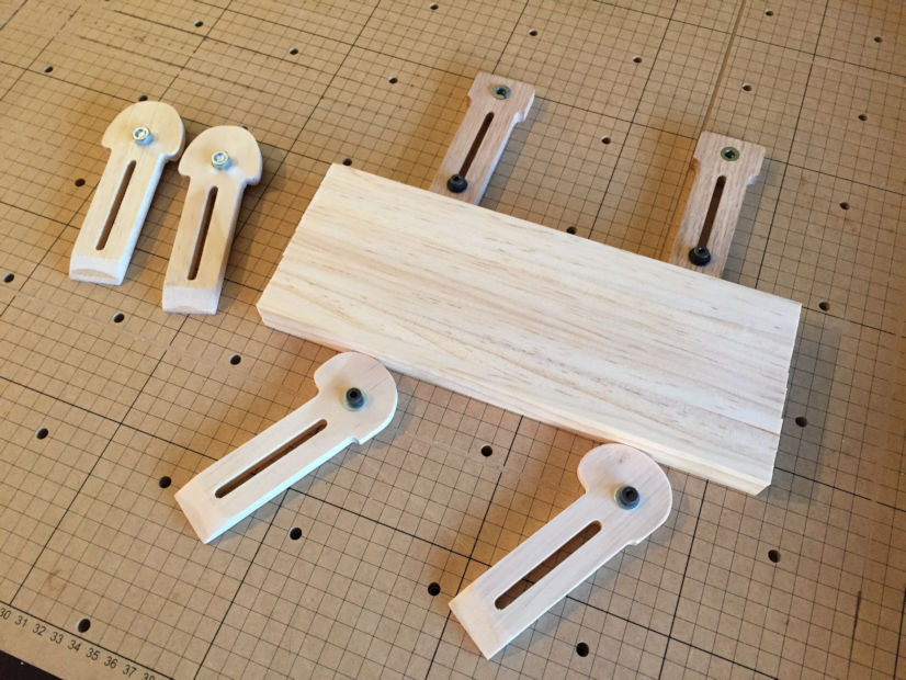
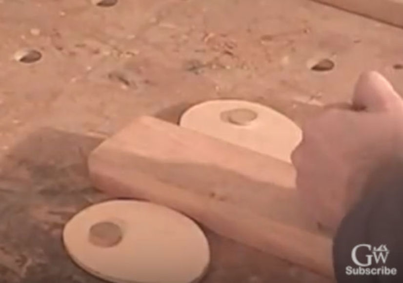
In previous examples you could see the cam clamp is in fact a type of lever we use to clench something by manual rotating the cam lever bar around the axes of rotation. At the first sight cam clamp seems like simple lever that rotates around axes, but lets take a look better at edges of that clamp in following pictures:
.
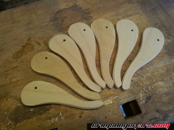
Now one can see our clamp is not just that simple as it looks at first sight: it's edge is formed by curved lines: especially in the last picture showing array of those lever bars ready for assembly.
Usage
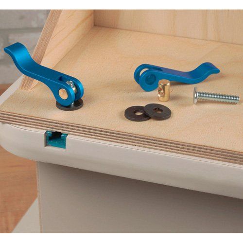
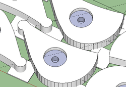
Either you believe it or not the cam clamps has unbelievably large implementation in all sorts of mechanical devices and especially in workshop templates, as can be seen from the following picturesque examples:

Initial demands for design
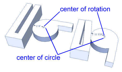
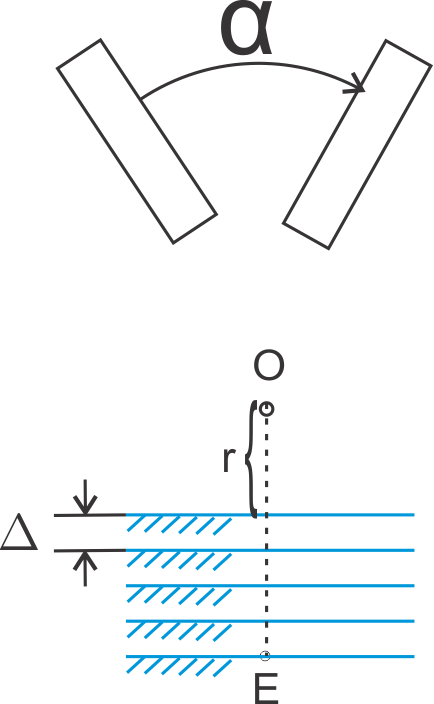
Shortly: what data do we need before starting any design process of cam clamp? That I have explained in the following picture:
|
О = the center of rotation. It's position in xOy is not known. r = the closest distance from center of rotation to the surface of workpiece. This variable is not know. In the lower part I have sketched the discrete reange of positions where the upper surface of workpiece can be. The workpice can in fact be somewhere between r to OE distance from the center of rotation. |
If those are the inital data, what is the task?
The task and design
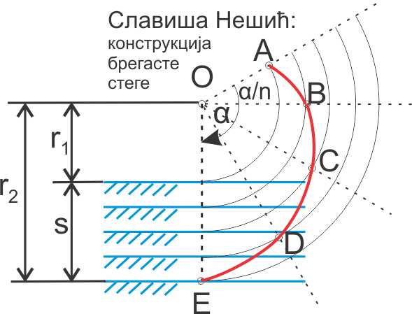
Let's take a look at the next picture. The task is as follows: for given range s where the surface of workpiece can be expected, and for the known angle α we need to find the variables r1 and r2. Easy, isn't it? Or maybe not?
|
By analyzing the picture on the left, I got the formula for the incident angle δ: \[\delta [rad] = \alpha - \frac{\pi }{2} - \frac{{\frac{s}{\alpha } \cdot tg(\alpha ) + {r_2}}}{{\frac{s}{\alpha } - {r_2} \cdot tg(\alpha )}}\] From the formula we calculate r2: \[{r_2} = \frac{s}{\alpha } * \frac{{\alpha - \pi /2 - \delta - tg\alpha }}{{1 + (\alpha - \pi /2 - \delta )tg\alpha }}\] Hence we solved the variable r2, and with it we have the value of variable r1=r2-s. With r1 we get the center of rotation as well and the task is solved. |
Based on the last formula we get the minimal dimensions of the cam clamp in the case of 90°:
| delta= | 3.5° | |
| alfa= | 90° | |
| s | r1 | r2 |
| 1 | 9.4 | 10.4 |
| 2 | 18.8 | 20.8 |
| 3 | 28.1 | 31.1 |
| 4 | 37.5 | 41.5 |
| 5 | 46.9 | 51.9 |
| 6 | 56.3 | 62.3 |
| 7 | 65.7 | 72.7 |
| 8 | 75.1 | 83.1 |
| 9 | 84.4 | 93.4 |
| 10 | 93.8 | 103.8 |
Dimensions of the minimal wooden cam clamp:
| delta= | 10° | |
| alfa= | 90° | |
| s | r1 | r2 |
| 10 | 25.4 | 35.4 |
| 20 | 50.7 | 70.7 |
| 30 | 76.1 | 106.1 |
| 40 | 101.5 | 141.5 |
| 50 | 126.8 | 176.8 |
| 60 | 152.2 | 212.2 |
| 70 | 177.6 | 247.6 |
| 80 | 202.9 | 282.9 |
| 90 | 228.3 | 318.3 |
| 100 | 253.6 | 353.6 |
The conclusion and the example
How do you use the last tables in practice? Suppose that you are working in wood and want to make a cam clammp that will cover the 32mm range of positions of the surface of workpiece. In second table for s=30mm you read that r1=76,1mm and r1=106,1mm. We assume r1=90мм and r1=90+32=122мм.
The rest is rutine: we draw the angle 90° on paper, we divide the angle to 3-4 parts. We draw two circles from the center of the angle with radius 90mm and 122mm. We locate the intersection of circles with the half lines dividing the angle and on half lines we determine the positions of cam clamp curve points proportionally from the center of rotation to the angle. Then we conect those cam lever points with smooth curves by visual interpolation and hence finish the drowing of cam clamp curve.
What is left is just to determine the optimal position of the handle part of cam clamp to fit the dimensions of available space. The requirement for the lever design is to fit the available space when rotating 90° and to be in suitable position for the human operator. The complete drawing is on paper and you have the blueprint for your design.
And finally of course, you go in your workshop and make that cam clamp finally!